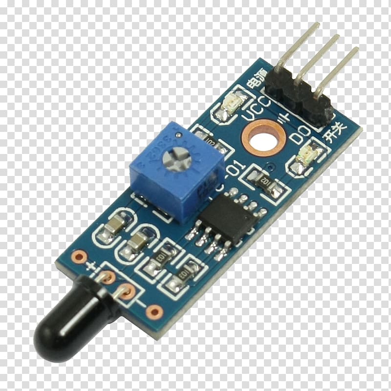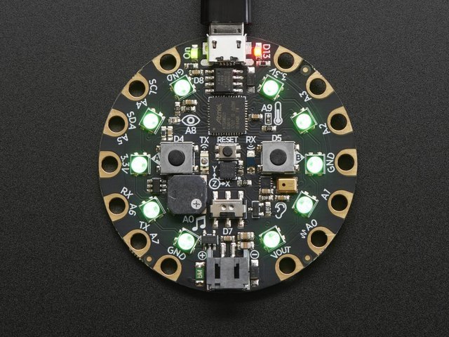
A way to receive the RF signal -> 433MHz RF RX module.A way to transmit the data -> 433MHz RF TX module.A microcontroller to process the data -> PIC16F688.A sensor to measure temperature -> LM34.A way to program the microcontroller -> ICSP.We need 2 block diagrams, one for each circuit.

One drawback I found, however, was that this library filled almost all my PICs memory. While doing research for this article, I found a site with a VirtualWire library for PIC's. The parity is being checked at the receiver end. Now, I'm adding parity check to the transmitted data. In this article, I'm using another technique ( this site inspired me). In previous articles, I have used an Arduino with the VirtualWire library, and I have used a "synchronizing" string in another. To sort out the data we want, we need some sort of protocol or error correction. The receiver will receive everything in its range. Sending data with the 433MHz transmitter is easy: in my case, I connect the PIC TX pin to the 433MHz data pin, then the transmitter sends whatever comes out the UART pin.īut receiving the data is the far more difficult part.

The receiver will receive the data, and display a message on an LCD. One microcontroller, the PIC16F688, will measure voltage from an LM34, convert it to an ADC value, and transmit some data.

In this article, I'll show you one way to make a wireless thermometer using two PIC microcontrollers. Other parts according to parts list below.433MHz RF modules (transmitter and receiver).A computer runnig MPLAB X, with XC8 compiler installed.Want a cool project for your PIC microcontroller? Read on! Requirements


 0 kommentar(er)
